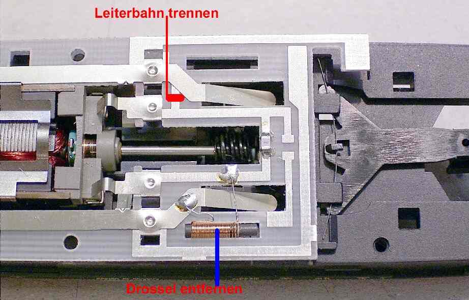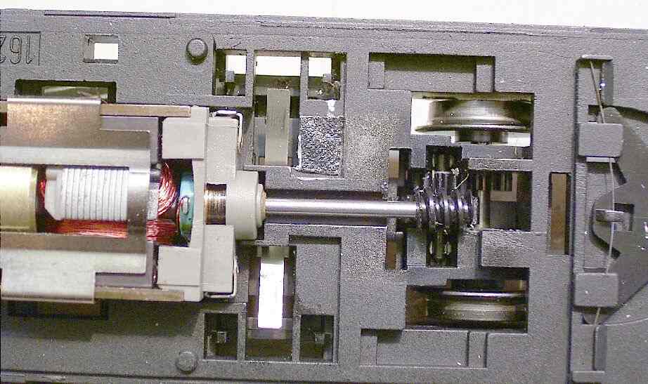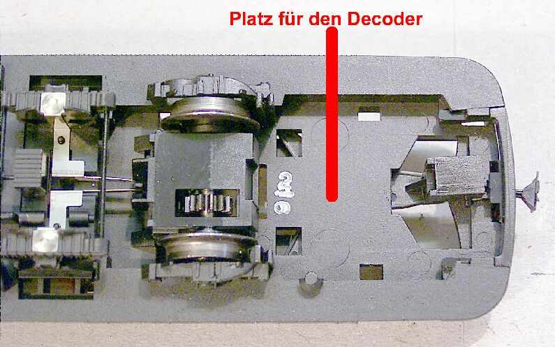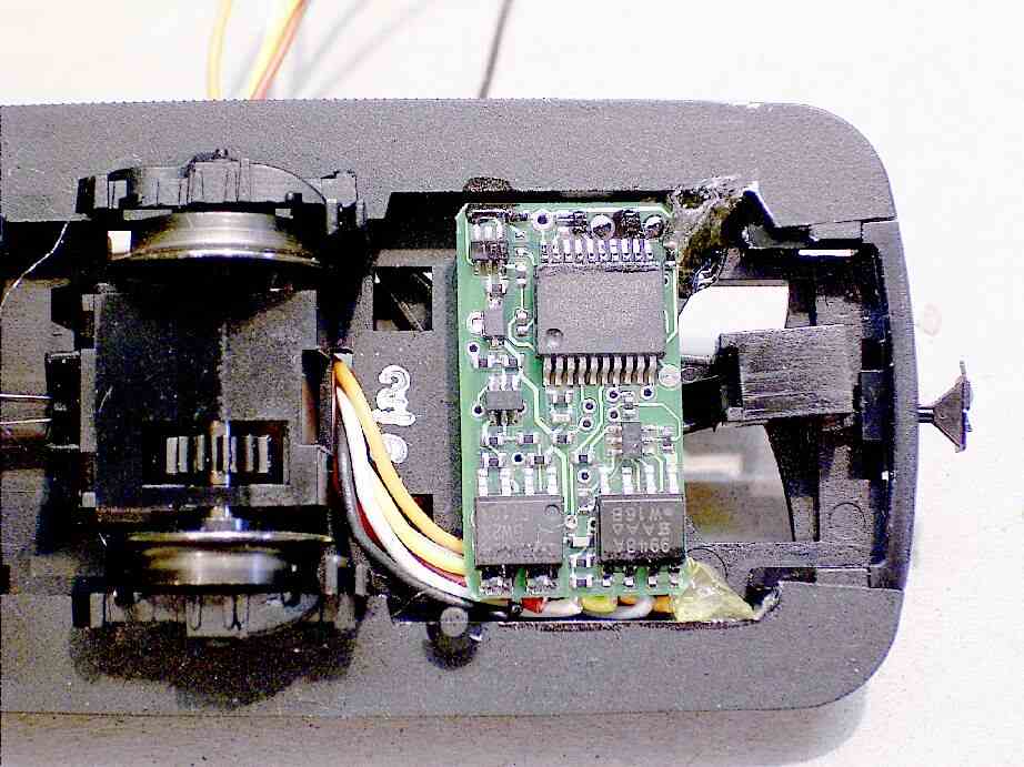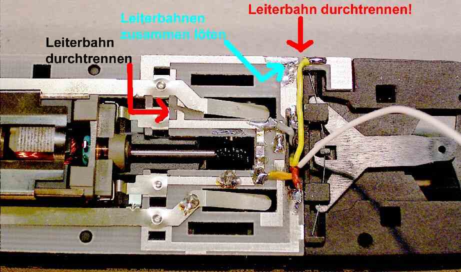
Der Unterschied zu dem schon vorgestellten Modell (VT 95 Fleischmann H0) auf der Platine ist der Motor jetzt mit der linken Schiene direkt verbunden. Bei dem anderen Modell ist dies genau anders herum.
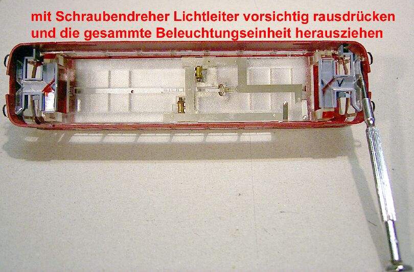
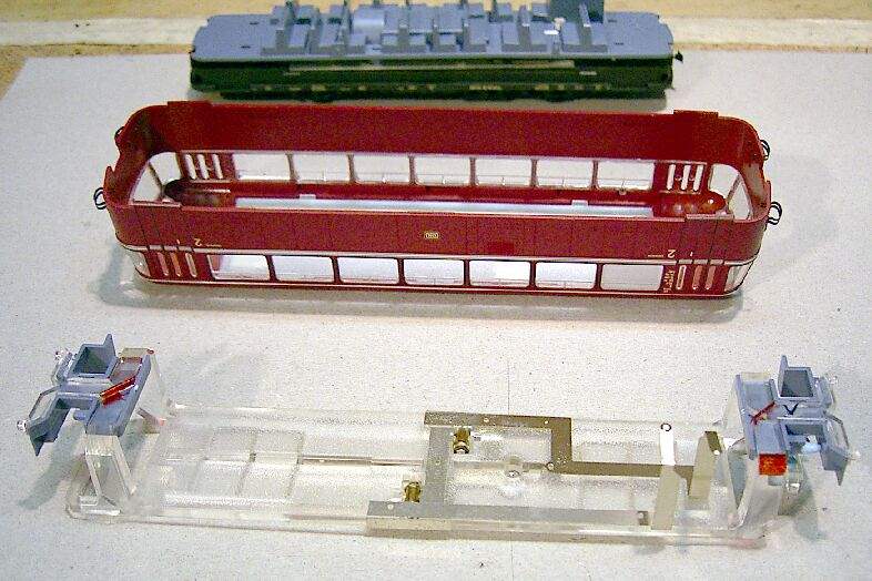
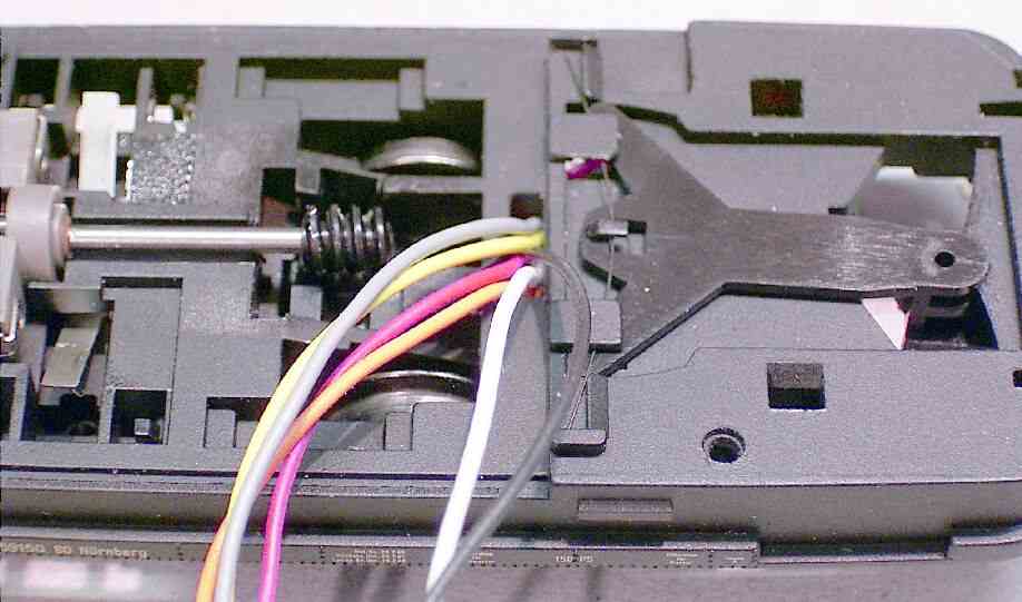
Gehäuseabnahme: Gehäuse wird gespreizt und vom Fahrgestell getrennt.
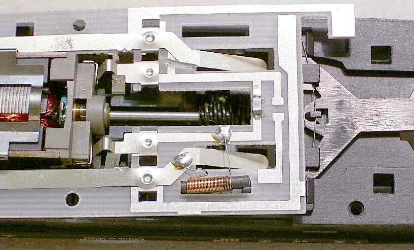
Auch hier denke ich, zeigen die Fotos alle Schritte.
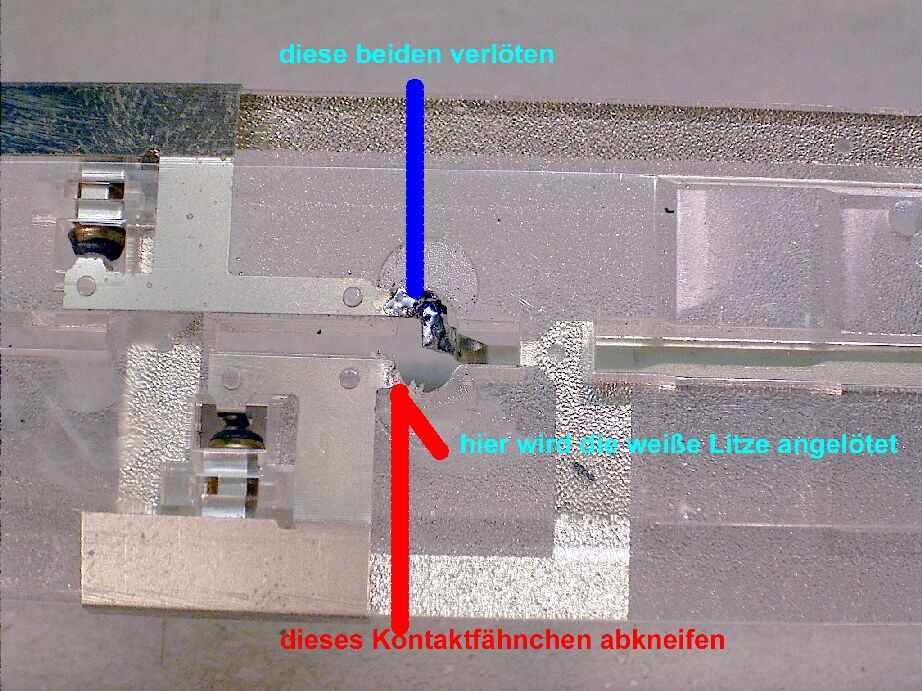
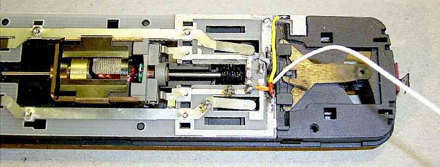
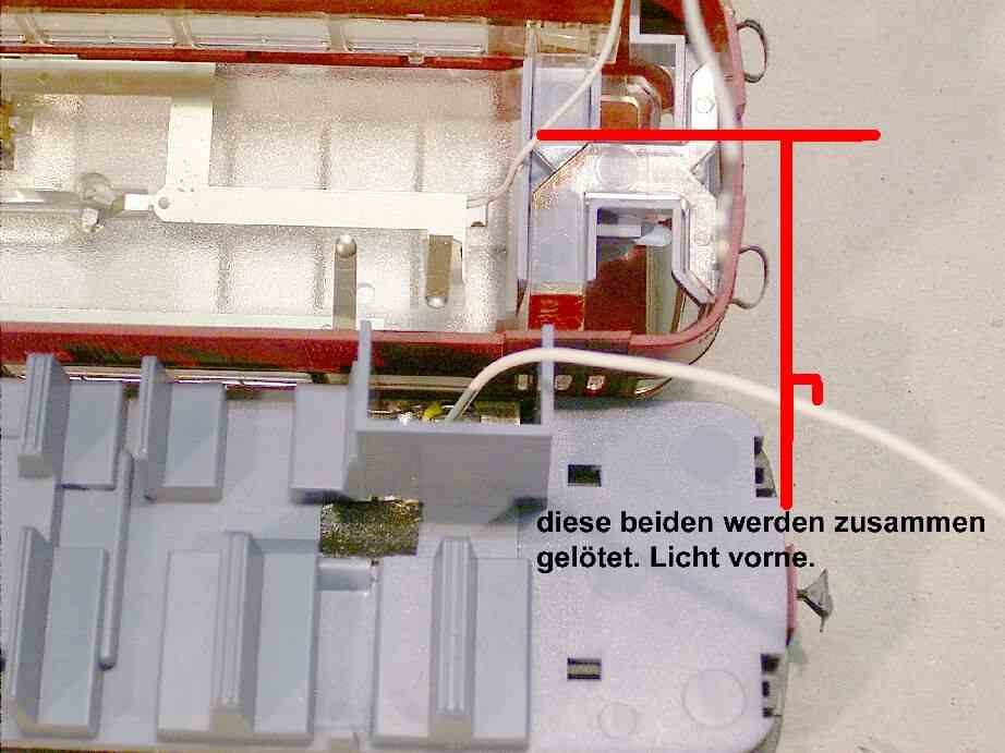
-Ergänzung zur Beleuchtung-
Da die Beleuchtung bei dem
oben angeführten Einbau doch recht schwach scheint, bedingt durch die
Masse-Abnahme von der Schiene, gibt es noch die Möglichkeit die Masse direkt vom
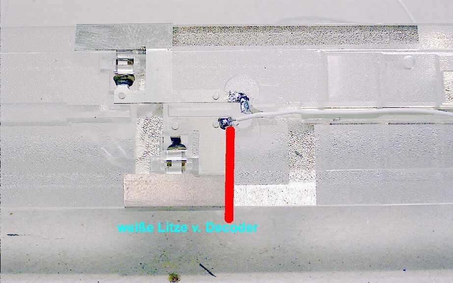
Decoder (blaue Litze) abzunehmen.
Dadurch erhöht sich die Spannung.
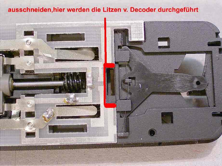
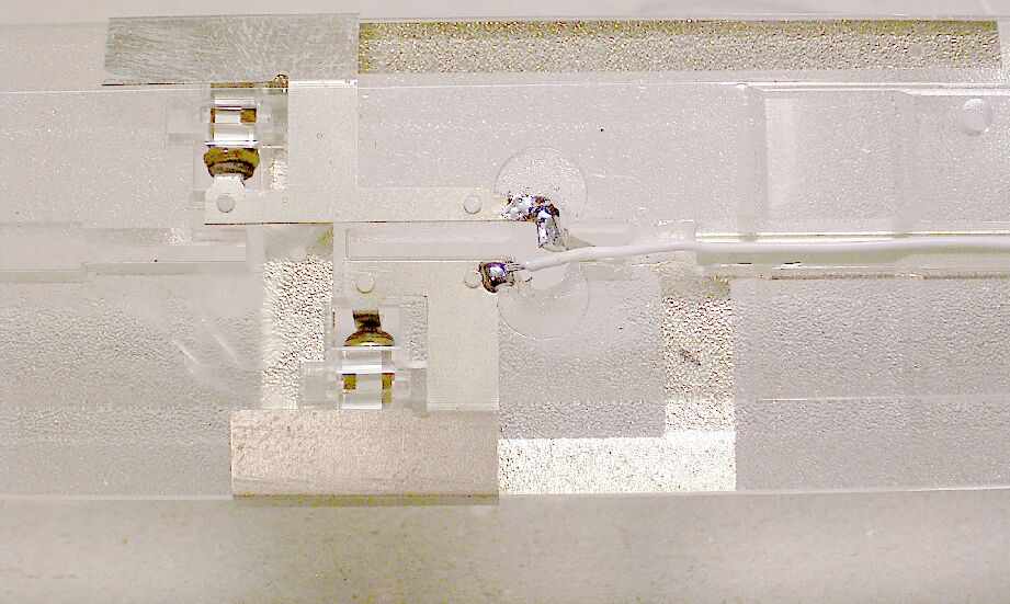
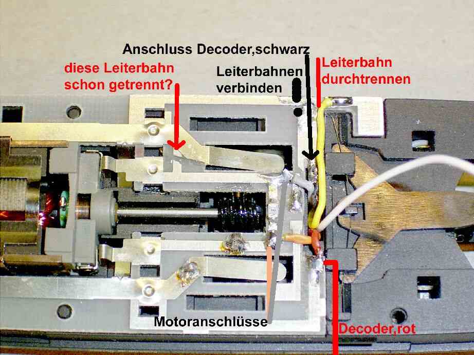
Der Anschluss der blauen Decoderlitze erfolgt dann (Bild 022)an die linke
Kontaktlasche( anlöten).
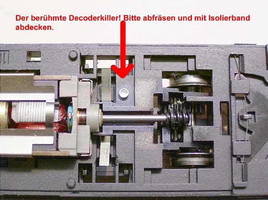
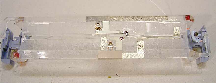
Die Kontaktfläche auf der Platine (Bild 003) oben links muss unbedingt mit Isolierband abgedeckt werden, sonst wird der Decoder zerstört!(Die Brücke (Bild 018) braucht dann nicht gelötet werden.
Viel Spaß wünscht
Hans-Peter